There are several DIY wind turbine science projects on the internet. This project is appropriate for the high school level and was originally sourced from http://www.velacreations.com a very good site, maintained by a couple living off-grid. Their site is worth a look. Another good website to visit for wind turbine projects is http://www.otherpower.com though these turbines can be fairly large.
We have included some modifications to the original instructions for a larger treadmill motor that weighs more, takes larger blades, requires better fastening for the blades, and uses a bearing to attach to the tower.
Making a wind-powered generator from scrap materials helps keep those materials out of the local dump. Most of the items you need can be found in your local hardware store, your garage, or from one of the “Freecycle” groups in your area.
Try doing a search on Google for “freecycle” to see what parts you can pick up for free. For the wind turbine built in these pictures, we picked up the motor on eBay for $10 plus shipping and the PVC pipe for the blades from a junk pile. The tail is made from an old roller paint pan.
Safety should be your priority. Your health is more important than a DIY project, so please follow all safety instructions you read, use common sense, and get help if you are unsure about something. Wind turbines can be heavy, dangerous machines, with fast-moving blades and the chance for electrical shocks.
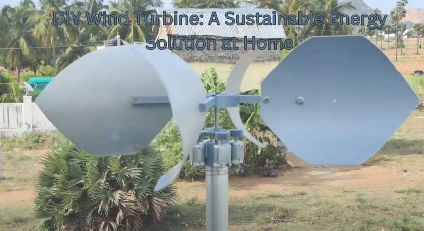
This wind turbine is based on the Chispito Wind Generator with its simple and efficient design and assembly. We have included several photos showing our changes, using the larger 20 amp motor.
Generator
The Permanent Magnet Generator (PMG) – You’ll need a PMG that produces at least 1 volt DC for every 25 RPM, thus if your wind turbine blades turn at 400 RPM it would generate 16 VDC. A 260 VDC, 5 A continuous duty Treadmill Motor with a 6-inch threaded hub is well suited for a small wind turbine. These motors are available locally and on eBay or other internet sites. You can get about 7 amps in a 30 mph wind. In other words, it is a simple, cheap little machine to get you started.
I picked up a 90 VDC, 20A treadmill motor off eBay for $10 plus shipping. This motor requires an upgrade to most of the original instructions due to the increase in size and weight. It also produces a lower output voltage. The motor is better suited for a system with gearing to increase the RPM.
You may use any other simple permanent magnet DC motor that returns at least 1 V for every 25 rpm and can handle upwards of 10 amps. The Ametek 30 is one of the best motors but is hard to find and the price seems to be getting rather high.
Try to find a motor that comes with a 6″ hub to attach the blades to – a circular saw blade with a 5/8″ shaft adaptor might work. For our larger motor, we initially used a metal slow-moving vehicle sign, bolted to a 3.5-inch pulley. The triangular shape was just what we were looking for.
We reinforced the sign with a wooden ring. This hub ended up blocking much of the wind on the smaller blades and we eventually switched to a six-inch wooden hub, reinforced with metal plating. When Hurricane Ike went through, that hub was also damaged. Thus we’d recommend a metal hub such as the saw blade or a used thick metal frying pan bottom.
Mounting the Generator
- 6 ft of “L” tubing
- misc nuts and bolts
- 3/4″ Self-tapping Screws
- For the larger 20Amp motor, I used a caster wheel with a hole in the center(Caster with a Hollow Kingpin) to attach the motor to the tower. This allows the heavy motor to turn very easily and doesn’t provide wear to the tower or flange.
Generator
- 90 VDC, 20 A continuous-duty Treadmill Motor
- 30 – 50 Amp Blocking Diode (one-way)
- 4 x 5/16” x ¾” Motor Bolts
- 8″ X 16″ PVC Pipe – or larger depending on the size of the treadmill motor (cover)
Tail
- 1 sqft (approx) lightweight material (metal) – used roller paint tray will work
- 2 X ¾” Self-tapping Screws to attach the tail
Blades

- 24″ length of 8″ PVC Pipe
- 6 X ¼” X 20 Bolts
- 9 x ¼” washers
- 3 sheets of paper and tape
Assembly
Cutting Blades – makes 8 blades (or 2+ blade sets) and a thin waste strip.
I have created a separate page with more pictures and expanded on this process a bit. After you’ve done this once, it makes sense. These instructions could use a little help for the first-time wind turbine blade maker.
- Place the 24″ Length of PVC pipe and square tubing (or other straight edge) side by side on a flat surface. Push the pipe tight against the tubing and mark the line where they touch. This is Line A.
- Make a mark near each end of Line A, 23″ apart.
- Tape 3 sheets of A4 paper together, so that they form a long, completely straight piece of paper. Wrap this around the section of pipe at each of the two marks you just made, one then the other. Make sure the short side of the paper is straight along Line A and the paper is straight against itself where it overlaps. Mark a line along the edge of the paper at each end. Call one Line B and the other Line C.
- Start where Line A intersects Line B. Going left around Line B, make a mark at every 145 mm. The last section should be about 115 mm.
- Start where Line A intersects Line C. Going right around Line C, make a mark at every 145 mm. The last section should be about 115 mm.
- Mark each line using a straight edge.
- Cut along these lines, using a jigsaw, so that you have 4 strips of 145 mm and one strip of about 115 mm.
- Take each strip and place them with the inside of the pipe facing down.
- Make a mark at one end of each strip 115 mm from the left edge.
- Make a mark at the other end of each strip 30 mm from the left edge.
- Mark and cut these lines, using a jigsaw.
Note: we also made a set of blades 38 inches long using the same measurement – only the length was changed – from 24 inches to 38 inches.
Sanding the Blades
You should sand the blades to achieve the desired airfoil. This will increase the efficiency of the blades, as well as make them quieter.
The angled (leading) edge wants to be rounded, while the straight (tailing) edge wants to be pointed.
Any sharp corners should be slightly rounded to cut down on noise.
Making The Tail
The exact dimensions of the tail are not important. You need about one square foot of lightweight material, preferably metal. You can make the tail any shape you want, so long as the result is stiff rather than floppy, we used an old aluminum paint tray (flattened).
Our 6-foot-long rail has holes already in it, so we will simply bolt the tail in place near the end of the rail – see instructions below about “balancing” the complete setup. Note that this design has no FURLING to take the blades out of the wind, in very high wind conditions. You can read more about furling designs here: FURLING YOUR WIND TURBINE
Drilling Holes in Blades – using the ¼” drill bit
- Mark two holes at the wide end and along the straight edge of each of the three blades. The first hole should be 3/8 ” from the straight edge and ½ ” from the bottom. The second hole should be 3/8 ” from the straight edge and 1 ¼” from the bottom.
- Drill these 6 holes – 2 per blade (3 blades in total)
Drilling Holes in Hub – using the 7/32″ drill bit and ¼” tap
NOTE: You may want to modify these instructions. Try replacing the hub with an old, used 7 1/4-inch skill saw blade. The larger surface area will give you more space to screw or bolt the blades. We also used 1/4-inch bolts rather than drilling and tapping holes. I’ve also seen old aluminum frying pans used for this purpose. They are light and solid!
- If the Treadmill motor comes with the hub attached, take it off, hold the end of the shaft (which comes through the hub) firmly with pliers, and turn the hub clockwise. This hub unscrews clockwise, which is why the blades turn counterclockwise.
- Make a template of the hub on a piece of paper, using a compass and protractor.
- Mark 3 holes, each of which is 2 3/8″ from the center of the circle and equidistant from each other.
- Place this template over the hub and punch a starter hole through the paper and onto the hub at each hole.
- Drill these holes with the 7/32″ drill bit.
- Tap the holes with the ¼” x 20 taps.
- Bolt the blades onto the hub using the ¼” bolts. At this point, the outer holes have not been drilled.
- Measure the distance between the straight edge of the tips of each blade. Adjust them so that they are all equidistant. Mark and punch each hole on the hub through the empty hole in each blade.
- Label the blades and hub so that you can match which blade goes where at a later stage.
- Remove the blades and then drill and tap these outer three holes.
Note: the metal slow-moving vehicle sign is not solid enough to stand up in high winds. We screwed on a wooden ring to the back of the sign to give it the required strength. This blocked too much wind so we ended up replacing it with a 6-inch wooden hub, reinforced with a metal plate on the back. Even later, we ended up replacing this hub with a 6″ metal hub for added strength.
Make a Protective Cover for the Motor
- Draw two straight lines, about ¾” apart, along the length of the 8 ” x 16” PVC Pipe. Cut along these lines.
- Make a 45º cut at the end of the pipe.
- Slide the cover over the motor and secure it in place.
Turbine Assembly
- Remove the rubber wheel from the Caster. Drill through the caster and bolt to your tower assembly (top pipe of your tower)
- Place the diode on the “L” tubing, about 2” behind the motor, and screw it into position using a self-tapping metal screw.
- Connect the black wire coming out of the motor to the positive incoming terminal of the diode (Labeled AC on the positive side).
- Connect the red wire coming out of the motor to the negative incoming terminal of the diode (Labeled AC on the negative side).
- Place each blade on the hub so that all the holes line up. Using the ¼” bolts and washers, bolt the blades to the hub. For the inner three holes, use two washers per bolt, one on each side of the blade. For the outer three holes, just use one washer next to the head of the bolt. Tighten. This points the blades away from your tower.
- Hold the end of the shaft of the motor (which comes through the hub) firmly with pliers, and turn the hub counterclockwise until it tightens and stops. Our motor didn’t come with a hub, thus we attached our “pulley hub” to the shaft.
- Attach the caster dolly to the motor and “L” rail. Balance this whole setup by moving the 1 square foot tail section along the 6′ long rail. Once you find the spot where everything is balanced, bolt the tail to the rail at that spot.
- For our larger (heavier) motor, we used a rotating caster with a hollow kingpin, bolted to the top of the tower. The dolly/caster needs to have a hole in the middle that you will run the power wires down, through the tower. The dolly is bolted directly to the DC motor which made the complete mounting system much easier.
For a longer life span of your wind generator, you should paint the blades, motor sleeve, mount, and tail.

On the larger 20A treadmill motor, we attached a dolly bearing directly to the bottom of the motor and then onto the top of the tower. Get a dolly wheel with a hole in the middle, which you thread the power wires through.
We also used the same PVC Blade Pattern to cut 3-foot blades. Just make the length 3 feet rather than 2 feet. The measurements at both ends stay the same – 145 cm wide sections that are next cut into 2 blades. This gives the same curve to the blades.
Depending on the size of your motor, you may want to experiment with different lengths of blades. Our larger blades were not balanced as well as the shorter blades initially and thus turned slower.
We cut them down in length from 36 inches to 32 inches and balanced them. To balance the blades, we placed the blades and hub, onto a long pointed nail. We then slid a washer along the blades to find the balance point. Then epoxy the washer in place (try to account for the weight of the epoxy as well).
How much power can we get from the wind?
Power AVAILABLE in the wind = .5 x air density x swept area x (wind velocity cubed)
Example:
Air density = 1.23 kg per cubic meter at sea level. Swept area = pi x r squared. Our 2 foot blades = 0.609m, 4 ft = 1.219m. 10 mph = 4.4704 m/s, 20 mph = 8.9408 m/s.
How much power is in the wind:
2 ft blade, 10 mph winds = .5 x 1.23 x 3.14 x 0.609squared x 4.4704 cubed
= .5 x 1.23 x 1.159 x 89.338 = 63.7 watts
With 4 foot blades and 10 mph winds = .5 x 1.23 x 4.666 x 89.338 = 256 watts
With 4 foot blades and 20 mph winds = .5 x 1.23 x 4.666 x 714.708 = 2051 watts
That’s the MAXIMUM power in the wind. However, it’s impossible to harvest ALL the power. The Betz Limit tells us that the maximum percentage of power we can harvest from the wind is 59.26%.
Thus our maximum power from these turbines would be:
2 ft blades, 10 mph wind = 37.7 watts
4 ft blades, 10 mph wind = 152 watts
4 ft blades, 20 mph wind = 1,215 watts
These values are the maximum power achievable. Your results will be less, depending on how well you shape the blades, how well-balanced the blade assembly is, drag going over the hub, copper losses, etc. A very well-built DIY HAWT would not likely get more than 50% of the above numbers.
If you’re interested in sustainable energy solutions at home, you might also want to explore DIY solar air heaters and the efficient models you can build.